
Modification to alignment chart for an un-braced frame.
Full description of the content.
The Nomograph equation for the unbraced frame is based on that assumption, This is a portal Unbraced frame, if the far end, considering the left joint is the near end and the right joint is the far end From the first sketch, the girder has a different slope than the second case.
The slope in the second sketch is due to the presence of the hinge at the right joint.
We will start to trace the modification to the un-braced frame for the three cases of end support. The three cases are shown in the next slide image. The bending stiffeness=EI/L for which we are going to derive the expression. For m, its value is by dividing the second case bending stiffness over the original bending stiffness, as in case 1, which is = 6EI/L.
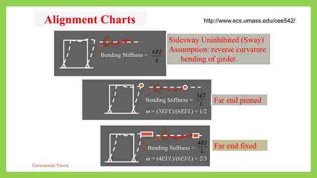
The m value for far end hinge= bending stiffness=(3 EI/L) / (6 EI/L )=1/2, this value is to be multiplied by the bending stiffness for the girder.
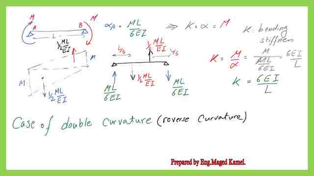
Let us review each case one by one. For the first case where we have a double curvature, we have an equal m value for each end. From the conjugate beam analysis, m is drawn at the tail of the moment, we can get the slope at each joint we can consider two triangles as drawn at each joint.
From M to zero, when the moment acts at the near joint, and from zero to M for the moment acts at the far end. the reaction of the moment will be the slope value, we have reaction =the area of the triangle area=1/2M*L where L is the span distance, the direction is upwards.
For the slope at the left joint the reaction of the moment, coming downwards, to get the slope at the near end, take moment at the far joint, the distance between forces=L/3. Here is the sketch we have 1/2*ML/EI acting upwards, we have 1/2*ML/EI acting downwards, and the slope at near end A =M*L/6EI, coming up.
The slope at the far end is B=M*L/6EI, coming downwards =M*L/6EI, The slope is downwards at the near end and the slope is upward for the far end.
This is the first case of modification to unbraced frame when the end support is connected. This is the first case, as shown in the elastic curve, the bending stiffness k is the stiffness when multiplied by the slope.
Modification to alignment chart when the far end is pinned for the unbraced frames.
Moment value K =M/α, α=M*L/6EI, M goes with M, K=6EI/L this is the normal condition. For the reversed curvature, let us have a look at the second case. where K=3 EI/L, we have a far end is pinned, the near end is acted upon by Moment M, so we have M at support A, zero moments at B. Then the slope α A=the reaction at A, which is the moment of 1/2 /EI multiplied by the arm distance/ span.
The reaction at Support A =(1/2M/EI)*(2/3)L, α-A=ML/3EI, this is the value of the slope at near joint A. This is the second case of modification to unbraced frame when the end support is hinged. The slope at the far support is α-B=ML/6EI, This is the sway of the portal frame.
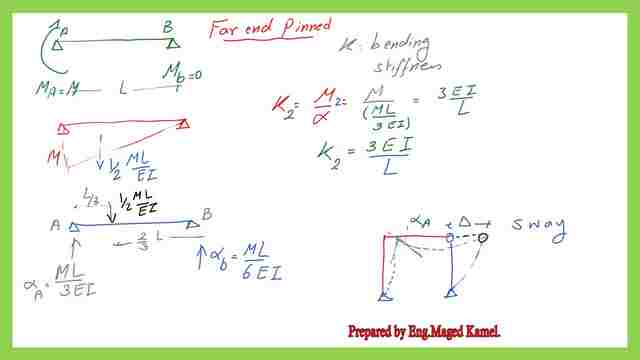
The slope here is different than the far end, hence no double curvature as before in case 1, then K the bending stiffness for case 2, if we let M= M2= M 2/αA=M /( ML/3EI) =M /( ML/3EI), k=3EI/L, k=3EI/L, this is the value of k for the second case, where far end is pinned, then m=1/2.
Modification to alignment chart when the far end is fixed for the unbraced frames.
The third case occurs when we have fixed support at the far end. as if we have a superposition of two cases, The moment at joint A=M, and again moment at support b=M αA= (the area of the moment)*arm distance/span, Area=1/2*MLl/EI /EI *the arm distance =2/3*L, αA=(M L/3EI), acting up, for the second slope at B, αb=(M L/6EI).
For the other part, the area of the triangle=1/2*ML/EI, and the arm distance=L/3.
This is the third t case of modification to an unbraced frame when the end support is hinged fixed. The remaining distance to A=L/3, the moment value at B =ML/4EI * L/3=ML^2/12, acting clockwise, then the slope=ML/12EI going down adding the two cases together.
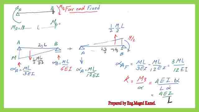
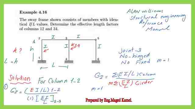
αA=(ML/3EI)-(ML/12 EI), α-A=(ML/4EI). The k value=M /αA, then we have K= 4EI/L. This is case number #3, m=4/6=2/3. Next time we will have a look at the solved problem- 4-16 from Prof. Alan Williams‘s book, structural engineering reference manual.
This is the pdf file used in the illustration of this post.
The Core Teaching Aids for Structural Steel Design Courses very use full data that can be downloaded from the AISC link. Check the folder for compression members.
This is a link to A very useful external link Concentrically Loaded Compression Members.
This is the next post, Solved Problem 4-16 For K Factor.