- Steel beams and types of buckling.
- What are the beams?
- Types of failures for a beam under a flexural moment.
- What is the difference between general buckling and local buckling?
- What is the difference between the major axis and the minor axis?
- What is LFB, local flange buckling for beams?
- What is WLB, web local buckling for beams?
- What is LTB, lateral-torsional buckling for beams?
Steel beams and types of buckling.
The topics included in the post.
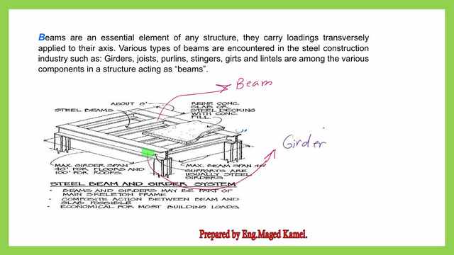
What are the beams?
Beams and girders may be part of the main Skeleton frames. Composite action between beams and slabs, slabs
transfer loads to beams, then beams transfer the load to the girders.
Girders are main beams supported by Columns. The secondary beams are called joists.
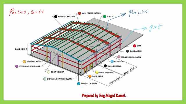
What are purlins and girts?
There is another sketch, we have a series of frames, and we have purlins, which are small C channels connecting between frames.
Each frame has a sloped portion, and the eave height is the height of the lowest level of the frame. Purlins are the form of beams, that carry the roof loads to the steel frames.
Girts are horizontal beams carrying loads from the block at the external sides of the steel frame, that carry the loads to the frame columns, as we can see from the next slide.
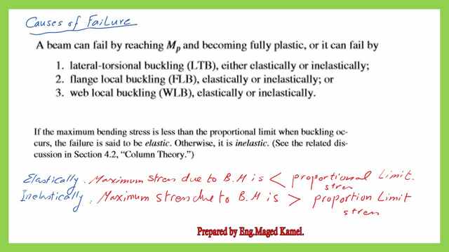
Types of failures for a beam under a flexural moment.
The next point will be the causes of failures for beams. lateral-torsional buckling LTB either elastically or inelastically. A beam can fail by reaching Mp, creating a plastic hinge. The failure can be one of the three types of bucklings as shown in the next slide.
1-( LTB) is the first reason for failure.
2- the flange local buckling (FLB). Elastically or inelastically.
3-The web local buckling (WLB), elastically, or inelastically.
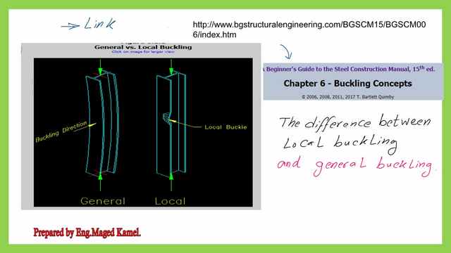
What is the difference between general buckling and local buckling?
A review of the buckling concept, to understand the difference between local and general buckling. The data is quoted from the following link.
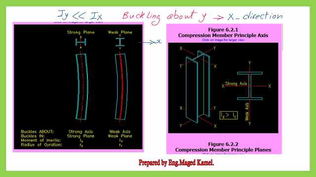
What is the difference between the major axis and the minor axis?
The major axis is the axis where the moment of inertia is higher than the minor axes, for instance for the I-beam section shown Ix is >Iy, which is why the x-axis is the major axis. To get the buckling shape, consider that buckling about the minor axis is in the direction of the opposite axis, which means that in this case, the buckling is in the x-direction.
What is LFB, local flange buckling for beams?
Let us check the moment of inertia about the y-axis, which is (hw*tw^3/12), and the inertia in the direction of x, which is tf*hw^2/12. To imagine the buckling direction about y.
Imagine a shift in the y-axis in the x-direction, the coefficient is called λweb=h/tw, where h is the height h web/ t web. hw=total depth d-2*kdes, or as the distance between the two rounded portions at the top and bottom flanges.
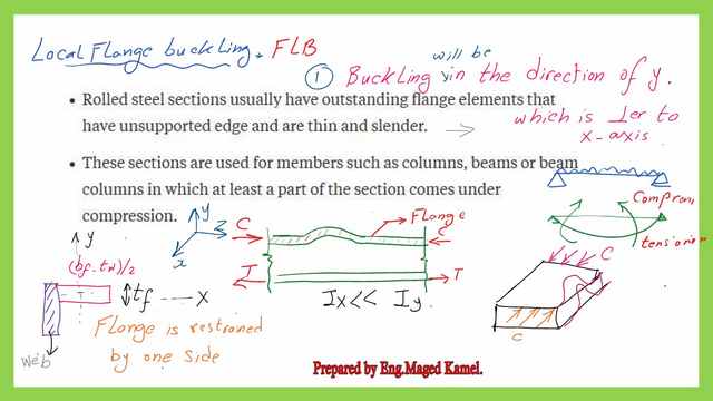
LFB, Local flange buckling for steel beams occurs due to the presence of a flange that has a thin unsupported edge, and has compression stresses due to bending; there is a possibility of buckling occurring in some locations; that is why it is called local buckling.
If we have a beam with an I-beam section, the flange of the section if we draw like this, the section consists of several plates.
The plate is acted by a compression force is due to the bending moment, which causes compression in the upper flange, while the lower flange will have a tension force.
This compression force acts on the upper flange, and acts on the upper flange, above the neutral axis, creating a lateral buckling as if the flange acts as a column. the flange is partially fixed by the web and acts in half-width. We might ask, the inertia is in the x-direction or the Y-direction? if we consider x as the horizontal axis, for the whole width of the flange, Ix =Bf*Tf^3/12, while, Iy=tf *bf^3/12, the lowest value will be Ix.
Buckling will occur perpendicular to the x-axis will be in the Y direction, and then localized buckling in
the flange will occur as shown as a curved portion, this curvature is called local flange buckling. A new factor will arise which is lambda f, λf =Bf/2tf, as a cantilever portion, while thickness is tf.
What is WLB, web local buckling for beams?
WLB, consider the web of the I section. The web local buckling, written as WLB will happen between the two flanges acted upon by a bending moment, which causes, compression force above the neutral axis.
The web is partially restrained at the top by the flange and by the tension in the web at the other edge the buckled shape will take the shape of a curve, around the vertical y-axis.
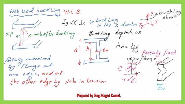
A new factor will arise which is lambda λw=hw/tw where hw is the web height and tw is the web thickness and can be shown as follows:
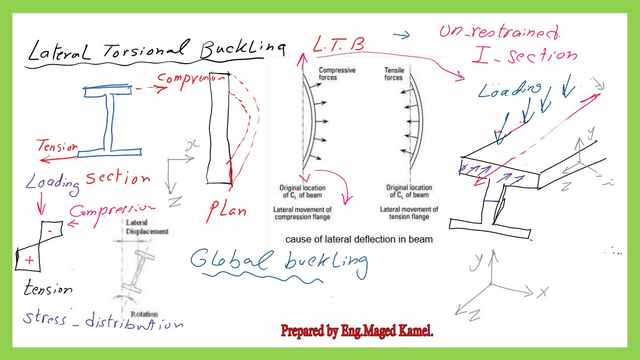
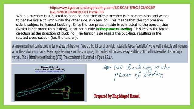
What is LTB, lateral-torsional buckling for beams?
LTB, Lateral torsional buckling, for steel beams happens due, which is acted upon by compression stresses at the connection of the upper flange, causes lateral buckling, that buckling is resisted at the other edge, which is restrained by the web in tension.
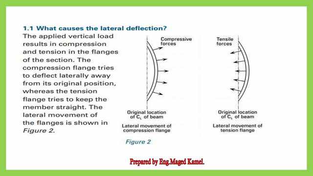
Here is more discussion about the lateral bending of the section.
Due to no bracing in the length Lower chord resists the buckling, since, it is under tension, while the upper chord has compression, accordingly, the compression force, as we can see causes bulging out.
While the tension force causes attraction to the inner side, at collapse the upper portion of the flange, moves outward, while the lower porting slightly moves outward as if you cause torsion to the section.
.
Then the steel section is displaced and also rotated by an angle, that is why it was called lateral-torsional buckling. why did it happen laterally? More data regarding LTB are shown in the next slide explained in the next slide.
This is the PDF data used for this post.
This is a link for the next post, Easy Approach to Compact and Non-compact Sections for Steel Beams.
This is a link for a good external reference for steel beams.-A Beginner’s Guide to Structural Engineering