Last Updated on September 12, 2026 by Maged kamel
Introduction to structural loads-LRFD and ASD.
Content of the post.
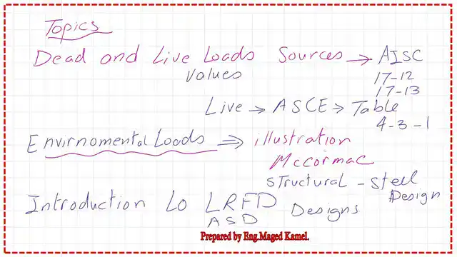
We’ll discuss dead and live loads, along with the associated tables of allowed live and dead load values. We’ll also include environmental loads. Next, we’ll learn how to create a load combination.
Two approaches will be employed. The first uses LRFD coefficients. LRFD stands for load and resistance factor design.
In this design strategy, we shall simultaneously increase the dead loads and live loads. We will reduce the element’s strength. As we will see later, strength reduction factors depend on the types of forces and moments acting.
The acceptable strength design is shortened to ASD. This design approach is a variation of the working stress, or factor-of-safety, approach. To determine the allowed stress in that working design method, multiply the yield stress by a safety factor.
Thus, the working stress design approach, or WSDM, has been modified.
Dead load is a structural load.
Table 17-12 on this slide lists the standard material densities we use to determine the dead load. We also offer cast and hammered aluminum, which weighs between 159 and 171 pounds per square foot.
Other materials include lead, copper, and iron. Our steel deck includes a manufacturer’s comment.
The stone is structurally lightweight and suspended; its weight is given in lb/sq ft.
Other items, like partitions and drywall partitions, contain studs and sheets.
There is a wall category for brick or CMU block. The 4-inch CMU blocks weigh 29 lb/square ft. The different finishes category is also provided, such as Terrazzo (1-inch), with a weight of 3 lb/ft2.

Live load as a structural load.
The next table source is ASCE-02. The title is the minimum uniformly distributed live loads((L0)) and the minimum concentrated live loads. The Access floor system office’s uniform loads are estimated at 50 lb/ft2. The corresponding KN/m2 is 50.0.
For the assembly areas and theaters, fixed seats are fastened to the floor. The uniform weight is 60.00 lb/ft2. The corresponding weight in KN/m2 is 2.87. For balconies (exterior). The uniform load is 100.00 lb/ft2. The corresponding uniform load in SI units is 4.79 kN/m². For corridors, the uniform load is 100 lb/ft2.
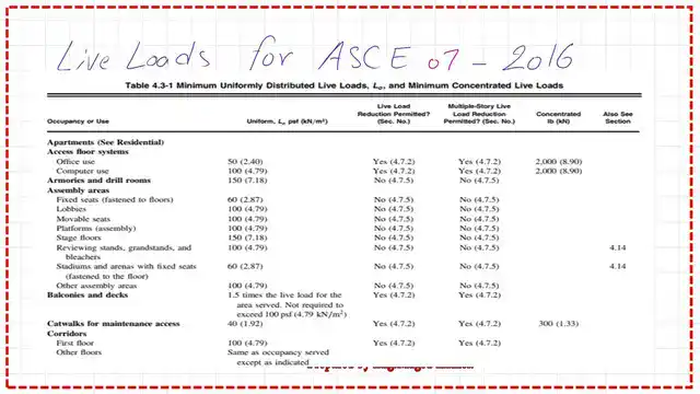
We continue checking Table 4- 11.. For hospitals, the operating room weight, as a uniform load, is 60 lb/ft2Equivalentnt to 2.87 kN/m2. Private rooms have a uniform load of 40 lb/ft2Equivalentnt to 1.92 kN/m2. For Office building live loads, file and computer rooms shall be designed based on anticipated occupancy.y For Lobbies, the uniform load is 100 lb/ft2Equivalentnt to 4.97 kN/m2.
Introduction to LRFD design
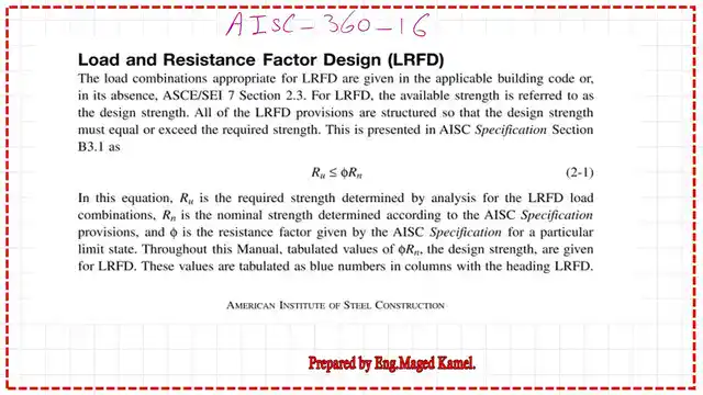
The next subject is Load and Resistance Factor Design (LRFD) LRFD is a method for designing structures so that no applicable limit state is exceeded when a structure is subjected to all appropriate combinations of factored loads A limit state is a condition in which a structure becomes unfit.
Structural members can have several limit states. Strength limit states concern safety and relate to maximum load-carrying capacity (e.g., Plastic hinge and buckling).
Serviceability limit states relate to performance under normal service loads (e.g., excessive Deformation and vibration). The formula may summarize the LRFD method as applied to each limit state.
Σγi Qi <=φRn. γi are factors that are multiplied by loads. Qs are loads, whether dead loads, live loads, wind, earthquake, etc Φi is a reduction factor for the strength Where R is the strength capacity of the member Φi is a reduction factor for the strength. R is the strength capacity of the member. The ultimate loads should be less than or equal to the modified strength.
Types of structural loads and related symbols.
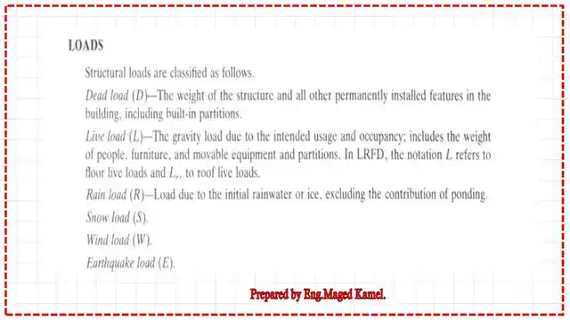
On the next slide, we will review load types and their symbols. We start with the dead load, denoted D. Next is the live load, denoted L, which includes the gravity load due to intended use and occupancy, such as the weight of people, furniture, movable equipment, and partitions.
In LRFD, the notation L refers to floor live loads, and Lr refers to live roof loads. R denotes Rain loads. The snow loads are indicated by S, and E denotes earthquake loads. Wr presents wind loads.
Environmental loads.
What are the environmental loads? Environmental loads are loads due to the environment.
Snow: In colder states, snow loads are often significant. One inch of snow is Equivalent to about 0.5 PSF, but it may be higher at lower elevations when snow is denser. For roof designs, snow loads commonly range from 10 to 40 psf. Snow loads increase when drainage is poor, leading to accumulation.

Rain as an environmental load.
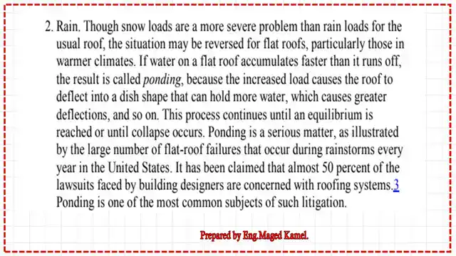
The second environmental load is Rain. Although snow loads are a more severe problem than Rain loads for typical roofs, the situation may be reversed for flat roofs, particularly in warmer climates. If water on a flat roof accumulates faster than it runs off, it results in ponding or accumulation of rainwater. Ponding causes the roof to deflect into a dish shape that can hold more water.
Wind as an environmental Load.
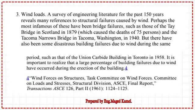
The third environmental load is the wind load. A survey of engineering literature over the past 150 years shows more references to wind-induced structural failures. The most infamous of these have been bridge failures, such as those of the Tay Bridge in Scotland in 1879, which caused the death of 75 persons.
Earthquake as an Environmental Load.
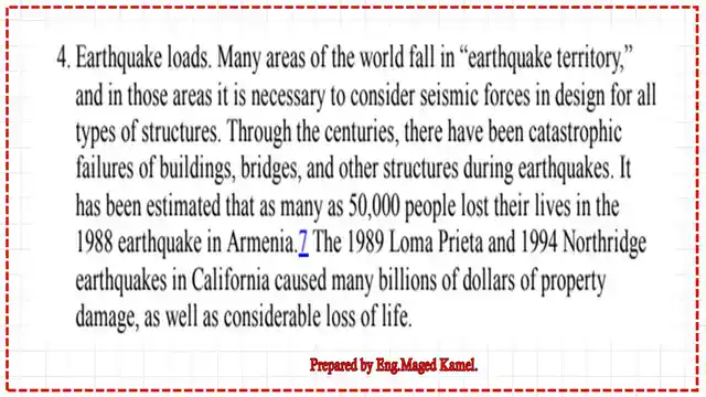
For earthquake loads, consider seismic forces in the design of all types of structures.
Another definition of the limit state.
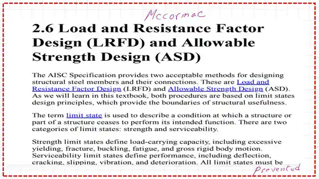
Another definition of the limit state is a condition in which a structure or part of a structure ceases to perform its intended function. Strength limit states define load-carrying capacity, including excessive Yielding, buckling, fatigue, and gross body motion. Serviceability limit states specify acceptable levels of fine performance, including deflection, cracking, slipping, vibration, and deterioration. All limit states must be prevented.
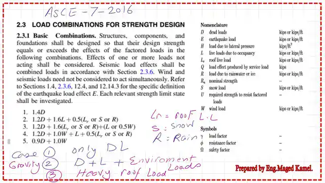
LRFD load parameters.
We will start by discussing the γi parameters. The first formula is 1.4D. This formula applies when only dead load is present. No other loads exist during construction, which is the case.
For dead and live loads in a structure, the formula is 1.2D + 1.6L, plus Rain load acting on the roof: 0.50(Lr, snow, or Rain). The biggest value is shown. The third formula is (1.2D + 1.6 (Lr or S or R) + (0.5L or 0.80W).
The loads considered are D& w&L&Lr and roof loads. Use the higher value, 0.50 L or 0.80 W. In the fourth formula, the wind direction is in the direction of the Dead load. The formula includes 1.2D + 1.3W + 0.5L + 0.5 (Lr, S, or R).
The earthquake acts in the same direction as the Dead load. We have 1.2D ± 1.0E + 0.5L + 0.2S; plus if E is in the direction of D, and minus if E is opposite D.
The abbreviations for all the loads used in the different combinations are on the right-hand side.
Symbols are γ load factor), φ resistance factor, and Ω safety factor.
D & L&W are not necessarily loads only; they could also be Shear forces or moments applied to a structure.
Torsional moments may also apply. For instance, if a given Moment due to a dead load is given, plus a Moment due to a live load, then 1.2D+1.6L means multiplying the dead Moment value by 1.20 and the live load Moment by 1.60.
Sometimes the Shear is given as Ql, the live-load Shear force.
For the live load case, multiply by 1.60. Sometimes, a factored dead load is given, meaning the load has already been multiplied by the load factor.
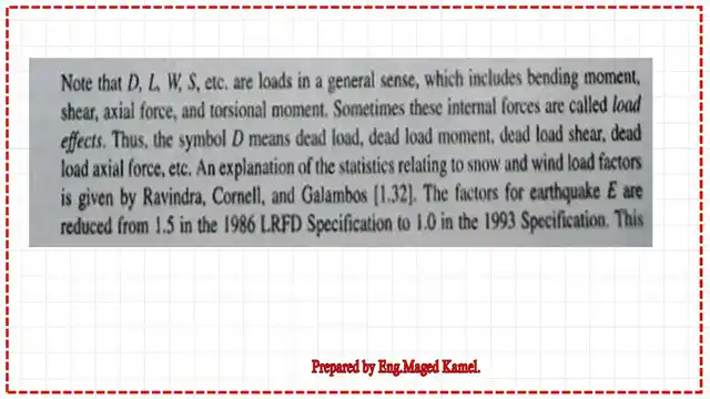
This is explained in the note, not that D, L, W, S, etc. Loads are, in general, those that include bending Moment, Shear, axial force, and torsional Moment. Sometimes, these internal forces are called load effects.
Thus, the symbol D denotes dead load, load Moment, load Shear, and axial force. For a Moment, we estimate the ultimate Moment as 1.2 Mdd + 1.6 Mll. The previous load factors, 1.4D + 1.7L, appear in earlier editions of the book.
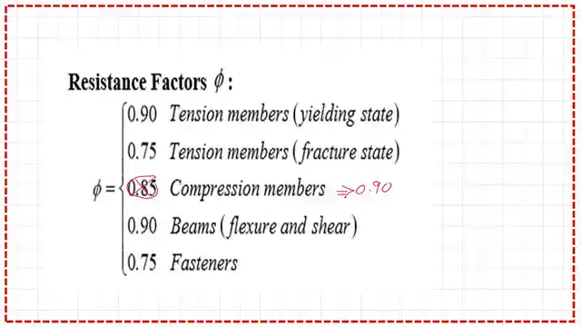
LRFD Resistance Factors
The reduction factor Φ is not constant; it varies with load conditions and member type (tension members, compression members, beams under flexure, and fasteners). Φ=0.90 is used for tension members (Yielding state), and Φ=0.75 is used for tension members (fracture state).Φ=0.90 is used for compression members.
ASD load parameters.
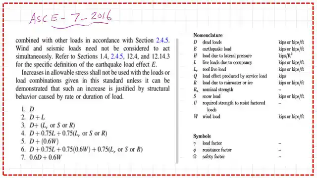
For the ASD Design method, the loads D, L, W, and E are not multiplied by the load factor. For the strength factor, instead of multiplying by Φ, divide by Ω, the safety factor, as shown. The first formula is ΣγQ .= D. The second formula is ΣγQ = D + L + H.
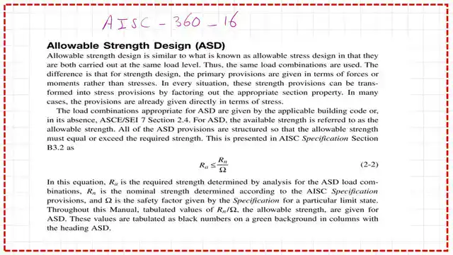
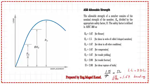
The third formula is ΣγQ = D + (Lr, S, or R) + H. The fourth formula is ΣγQ = D + 0.75L + H + 0.75(Lr, S, or R). If we plot the relationship between displacement and load, the nominal strength is Rn.
In LRFD, we multiply by φ to obtain φ*. In the case of ASD, we divide by Ω, which is 1.67 for the Moment. The Moment of Inertia Ω is shown on the slide: Ω = 1.67 for compression. = .67 in the case of tensile Yielding.
The initial slope of the curve is linear from zero to the yield stress. Thee ASD value =Rn/Ω.The relation between the Ω value and Φ is 1.50/Φ=Ω If we have Φ = 0.90 in bending, 1.50/0.9 = 1.67 is the bending reduction factor in the ASD design if the Live load equals 3 times the Dead Load value.
To see the major changes between CM #14 and CM #15 regarding the different grades of steel and their uses in steel elements and bars, refer to post 1A.
You can review or download the PDF for this post from the following documents.
In the next post, we will solve an example using the different load factors for LRFD and ASD designs.
This is a link to a very good reference: Chapter 1 – Introduction–An Overview of the AISC Steel Construction Manual, 14th Edition.
This is a link to a very good reference: Chapter 1 – Introduction–An Overview of the AISC Steel Construction Manual, 15th Edition.
This is a link to a very good reference: Chapter 1 – Introduction–An Overview of the AISC Steel Construction Manual, 16th Edition.