Steel columns and Euler’s formula-part 2.
In this post steel columns and Euler’s formula-part 2, we will discuss the different shapes of steel columns & how to derive Euler’s formula, and lately the modes of failure for columns.
Different shapes of steel columns.
The first shape is the single angle. The second shape in b is double angle back to back and the in T section and w columns etc. And the round shape, he started talking about each element and where to be used, for instance, single angle member section a that is used as bracing and as a compression member in a light truss. Equal angles are more economical than unequal angles, because these have their least r values are greater for the same area of steel.
The double angles are likely to be used in trusses as a top chord that might consist of pair of angles back to back for section b.
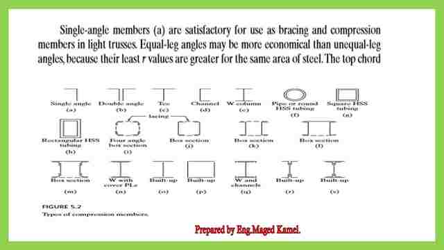
The angles are spaced for the insertion of the guest plate, which is why they will be back to back. An examination of this section will show that is probably desirable to use unequal leg angles with the long legs back to back.
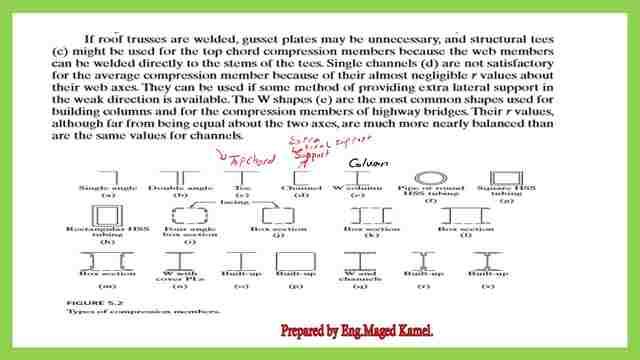
If you wish to have extra lateral support, use the C channel. For w sections are suitable for can be used as columns for buildings. and for compression members in a highway bridge. there are different values for the radius of gyration values.
Derivation of Euler’s formula.
We are all familiar with the double integration method. Euler’s formula depends on the estimation of the moment caused by a compression force P*y= E*Iy”, where y” is the curvature.
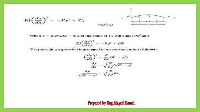
1-Multiply by 2*dy, Integrate one time to get the expression for the deflection since this equation is in the general form.
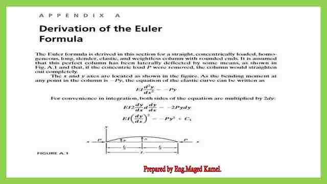
2- then from the boundary condition, establish a value for C1 by considering- dy/dx=0 at L=L/2.
3- After several mathematical operations, we get the value for The critical load Pcr that the column can carry.
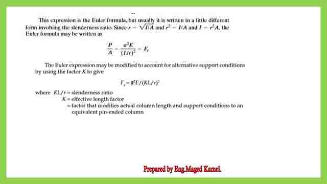
The critical buckling load
P =π^2 EI/L^2, where Pcr is the critical buckling load, which is the load is the max load that the column can carry, and then the stress For can be estimated by dividing the critical load / the area and recall that the Inertia I can be expressed as the multiplication of A*r^2.
The stress can be evaluated as Fe=π^2 EI/(L/r)^2, which can be written as Fe while getting this expression as assumed that the curve starting from zero at end support and increasing to the delta, at the middle and then he got that expression.
But in reality, several different end conditions are there, which is why the k expression is introduced in the expression then the L can be rewritten as ( k L), as a result. The equation of Fe will be set =π^2 E/(KL/r)^2, where KL/r is called the slenderness ratio, K is the effective length factor, that modifies actual column length, and supports conditions.
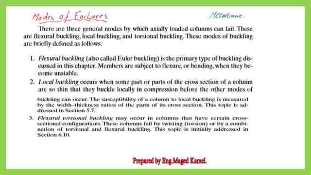
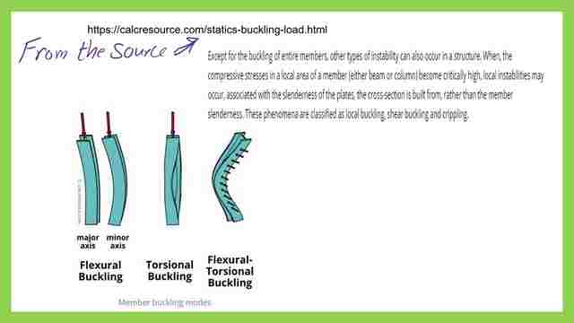
Types of modes of failure.
Compression members can fail in three general modes of failure:
1-Flexural buckling, or Euler’s buckling, the members will buckle about the least radius of gyration for the section.
2- Local buckling, some parts of the cross-section will buckle locally in compression.
3-Torsional buckling for members that have a certain cross-section configuration.
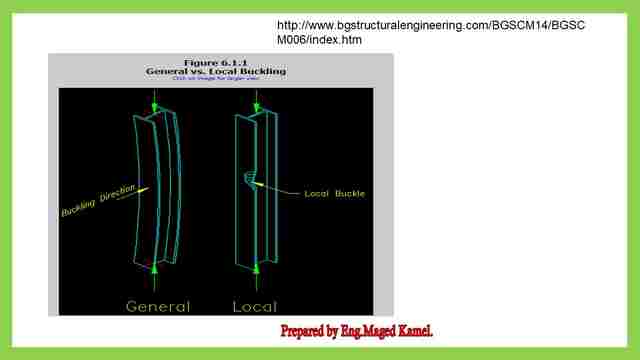
This image gives a better understanding of the failure modes of compression columns.
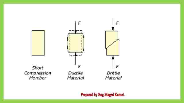
The modes of failure for short columns.
There are two modes of failure, ductile failure will be having short bulged shape while brittle failure will have a shear failure with a slanted angle.
This is the pdf file used in the illustration of this post and the previous post.
For the next post-2-Buckling for columns – effective length factors.
For an external resource-chapter 7– Concentrically Loaded Compression Members