Introduction to Tension members.
Introduction to tension members- tension yielding.
We will begin a new subject, Introduction to Tension Members.
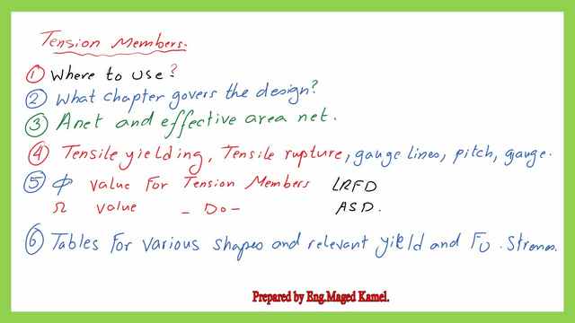
The first section discusses where to employ the tension members.
The second item is the AISC chapter, which regulates tension member design.
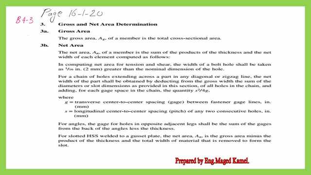
The third item is an explanation of net and gross areas. The gross area is the section area without considering any deductions for fasteners.
The net area is the section’s area minus the fastener’s area. Later, we’ll look into fasteners like bolts for allowances.
There are net and special tables for determining the final value of the effective net area.
The fourth component discusses tensile yielding, tensile rupture, and gauge line information.
The fifth component provides the design parameters for tension members in the LRFD and ASD, the reduction factors φt and Ωt.
The sixth item is the tables for various shapes and the relevant yield and F ultimate stresses for tension members.
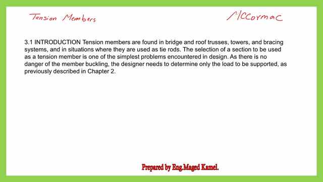
Tension members are used for bridges and roof trusses, towers, and bracings. Tension members are considered when used as tie rods.
Selecting a section to be used as a tension member is one of the simplest problems encountered in design, as compared with columns and beams, so, the design of the tension members is considered to be simple.
As there is no danger of the member buckling, the designer needs to determine only the load to be supported, like whether the ultimate load is 1.4 D or 1.2 D+ 1.6 L, then choose the biggest values, as for the LRFD design, or D+L as for ASD design.
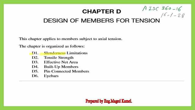
The related division in the specification for Tension members.
The next slide includes the chapter used for the design of tension members, then which section in the chapter for tension members is shown. Chapter D is used. D-2 governs the Tensile strength. AISC-360-16 page 16-1-28.
There are two items, Tensile Yielding and Tensile rupture. For the tensile yielding, the P nominal is estimated as equal to the product of Fy*Ag, Fy is the yield stress, and Ag is the gross area.
For the design strength multiply by φt =0.90. While for the allowable strength multiply by (1/ Ωt) where Ωt=1.67.
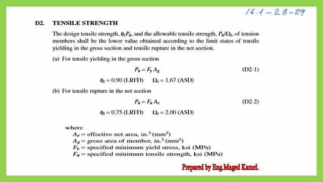
Item b) is for tensile rupture at the places of bolts or welds. The nominal load Pn = Fu*Ae, where Ae is the effective area.
However, the LRFD parameter is different and is φt =0.75, less than the value given for tensile yielding.
For the ASD design, based on the relation of φ*Ω=1.5, then Ωt=2.00. Fy is yield strength and Fult is the ultimate strength. D-3 includes the effective net area and is to be estimated from B 4-3, Aeff=Anet*U factor, U, shear lag factor=1.
In the next slide, we can see that there are two cases, the first case is when the two members are connected fully like a bolted plate and spliced channel the effective area equals the net area, and the u factor, shear lag factor, equals one.
Whenever two channels are connected only at the upper and lower flange, while the web areas are not connected the the effective area will be considered smaller than the net area and the U value will be less than one.
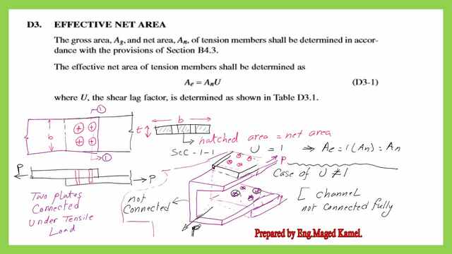
This is the provision from the AISC code for the net area for tension members and the different terms used.
The shear lag factor U value is obtained from Table D3-1.
Tension yielding.
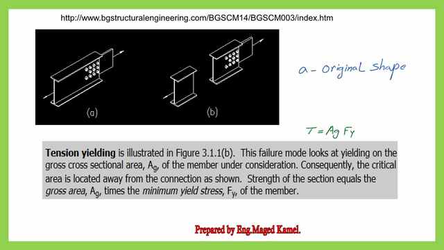
Tension yield picture Quoted from The external link. A BEGINNER’S GUIDE TO THE STEEL CONSTRUCTION MANUAL, 14TH ED.
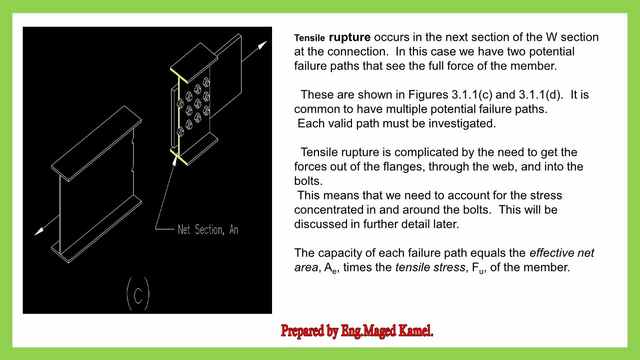
As an introduction to tension members, we would want to examine the various modes of failure.
There are many good illustrations, such as a section for the W section; if we deal with tension yielding, there is a failure mode. On the positions distant from the bolts. When tension forces are applied from the ends, the failure will occur at a position other than the bolts’ path.
This failure mechanism focuses on yielding in the gross cross-sectional area.
T=Ag*Fy calculates the tension force at failure. an is the original shape, and b is the shape after the section’s tension yielding has occurred.
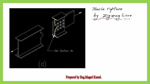
Tensile Rupture types.
This is The first failure was a vertical line passing by the line of the bolts in the direction that is perpendicular to the force direction.
The second failure is shown here as a zigzag line, from which the net area was estimated. for which we have to consider the spacing S and the perpendicular distance g between bolts.
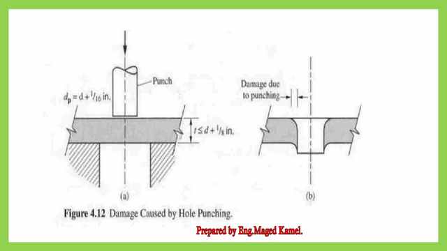
The damage occurs due to the Punching of a hole.
As can be shown punching for bolts, can cause damage around the bolt and create extra diameter that should be taken into consideration while estimating the net area.
It is advised to add 1/8 inch to the diameter of the bolt to account for damages .
This is the PDF used for the illustration of both posts 1 and 1A from this link.
The next post contains an Easy introduction to Tension members-part-2.
For a useful external Chapter 3 – Tension Members– Bartlett Quimby