
Collapse Load For A Simply Supported Beam.
A solved problem for collapse load for a simply supported beam under concentrated load.
We continue the discussion of the plastic theory, for the viewers for the first time, refer to the two videos civil 120-8 and civil120-9 to take an idea regarding the plastic theory.

We have a Simply supported beam, which has hinged support at joint A and one roller support at B, the beam carries a concentrated load P acts at the middle of the span and the span length=L.
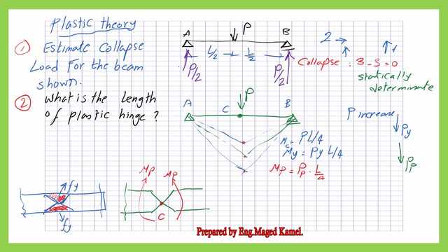
It is required to estimate the collapse load for the beam shown. Due to the collapse of this beam, a plastic hinge is formed, it is required then to estimate the length of that plastic hinge.
To create a mechanism, we need to check the beam under question. Check the degree of indeterminacy and then add 1 to create a mechanism of collapse in which the beam will collapse.
We have two reactions at the hinged support and the reaction of the roller support equals =1, 2+1=3, we have three degrees of equilibrium equation, then subtract the equilibrium equation from the total reactions, 3-3=0.
We need to convert the beam from a statically determined Stable system to an unstable beam to create the mechanism of collapse by providing an additional hinge.
The suggested place to add the hinge is at the load location, where the maximum moment occurs.
At the Mid-length of the span, when load P gradually increases from zero till it reaches Py. As a reminder, the reaction at both supports is P/2, and the bending moment at L/2 =P*L/4.
In the diagram of the bending moment, this is the moment at point c, Mc=P*L/4 which is < My, when P=Py, M at c=Py*L/4. For further increase of load to P plastic, the moment at point c will be Pp*L/4.
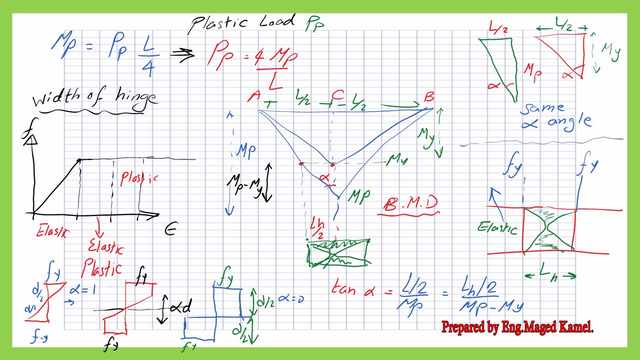
If we refer to the strain stress relationship, the stress can be represented by linear relation, where the uppermost fiber will have a stress =Fy.
For the second stage the stress becomes elastic-plastic, the stress at the top is Fy, and part of the upper fiber stress will be increased to Fy. At the last stage, the stress of the whole section is = Fy.
How to estimate the Collapse load for the beam?
For the shown section, at point c, where the plastic hinge is formed, the top fiber is stressed to Fy, it can not carry more stress when load increases, a further increase of load will cause the lower fiber to be stressed to Fy at that point, the stress =Fy, a hinge is formed. At the hinge, there will be moment a=Mp at both sides of the hinge.
This is the mechanism of failure where the moment reaches Mp. The plastic moment value is Mp=Pp*L/4 when the load is =Pp when the load is =Pp=4*(Mp/L).
How to estimate the length of the plastic hinge?
If we place the section of hinge below the bending moment diagram. The Moment diagram is represented by a zero st hinge to Mp at the center, from 0 to Mp. Draw a horizontal line by the value of My, it will intersect with the moment diagram at the point located at Lh/2 from point c, and the same value for the Lh/2 to the right of point c.
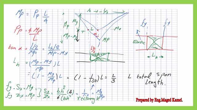
The vertical distance between Mp and the horizontal line is=Mp-My. We will estimate tan α, to create an expression for Lh, tan α=(L/2)/Mp. The same tan α= (Lh/2)/ /(Mp-My). We adjust to get the final expression for Lh.
Equate L/2/Mp=Lh/2/(Mp-My), Lh=L*(Mp-My)/Mp=(1-My/Mp)*L, for a rectangular section My=Fy*Sx, while Mp=Fy*Zx, dividing My/Mp it will be=Sx/Zx, I corrected the writing, Sx=b*h^2/6, Zx=b*h^2/4. My/Mp=1/1.50. Lh=(1-(1/1.50))*L=L/3. The horizontal length of the hinge =L/3.
The virtual work method.
The virtual work saves time since by using this method, no need to estimate the bending moment values.
Drawing the two bending moments together as in the case of the static method, in the case of a fixed end beam, where we draw the two-moment diagrams for the fixed moment at Mp and the positive moment Mmax= Mp, at the hinge. We equate both to the total applied moment.
For the virtual work, we equate the external work to the internal work. External work= P*Δ, which is the product of the load by the deformation Δ at the plastic hinge due to the mechanism of collapse. Mp is obtained, due to deformation Δ, an angle α is developed.
which is the product of the load by the deformation Δ at the plastic hinge due to the mechanism of collapse, Mp is obtained due to deformation Δ, and an angle α is developed.
We can consider that tan α is =α since α is a small angle. The external work at the LHS, but the work due to Mp=Mp* total angle (2*α),2*α is the change of Angle. This is similar to the yield line analysis for slabs.
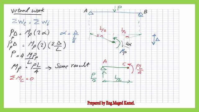
The internal work= 2*Mp*α, where α=Δ/(L/2), P*Δ=2*Mp*2*Δ/L, Mp= Pp*L/4. For the sum of the moment at the hinge=0, then P/2*L/2= p*L/4 in the clockwise direction will balance with M=P*L/4.
A solved problem for a simple beam, how to estimate the Collapse load for the beam?
Using the given sections all of A992 stee, and the plastic moment, determine the value of Nominal load Pn for a W18x76 section. using the Upper theorem we equate the product of Pn*Δ by Mn by 2θ. The Pn is equal to 84.895 Kips.
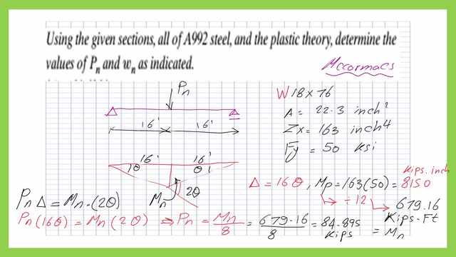
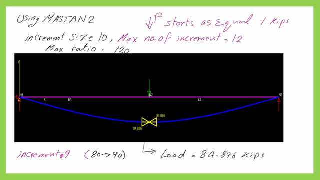
Using Mastan2 to verify the previous result, use P start load of 1 kip maximum ratio is 120. The nominal load is found to be equal to 84.895 Kip[sa for the Given W18x76 section where Fy=50 Ksi
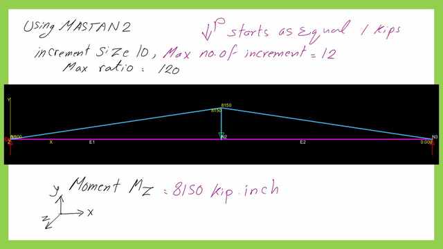
The value of Plastic Moment is equal to 8150 kips. inch, the next slide image shows the given value.
This is useful data about the structural analysis -III.
For the next post, Collapse load for indeterminate beam. how to get the collapse load for an indeterminate beam?