Two Solved Problems For Column Analysis.
This is a brief description of the post content.
Two Solved problems for steel column analysis.
Two solved problems for column analysis, the first problem is a problem this is similar to the solved problem 13.28 which we solved earlier in the previous post, but this time I have changed the dimension from W 12×50 to W14x61.
The column is fixed at one end and has a guide roller at the other end which is at the top. This is the table for the different values of k based on the end condition for columns. This problem is quoted from the printed problems from M Iqbal Book for the F E exam review.
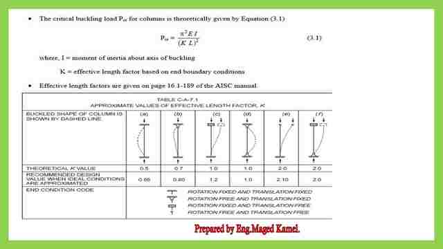
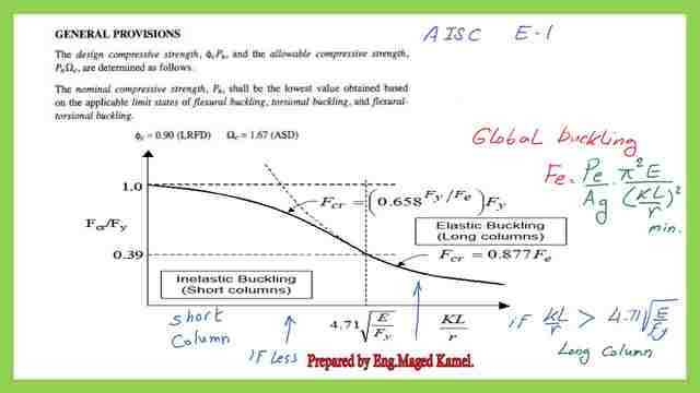
First, we will review the k values for the six cases of columns with different end conditions. This is the general provision E-1 from the AISC code, for the graph between Kl/r and Fcr/Fy.
We are going to continue with the previously solved problem 13-28, it will be considered as 13-28a. But after making some Modifications, for the solved problem 13-28a, the column is chosen to be W14x61,Fy is 50 KSI.
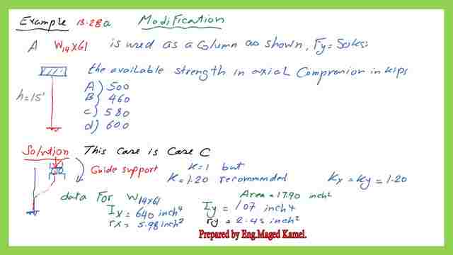
What is the available Strength in axial compression in kips? Which value of the 4 alternatives, listed from option A to option d.
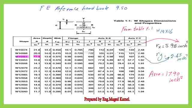
The support case of a column is case c, where the support is fixed at the bottom and guided support at the top Our kx=ky=1.2 as recommended. For the needed information for W14x61, the area is 17.90 inch 2, the value of Ix =640 inch 4, and the radius of gyration about the major axis rx= 5.98 inch2. Iy= 107 inch4 and ry =2.45 inch2.
The procedure is to evaluate the kx and ky. From the previous example our KyLy=18 feet.
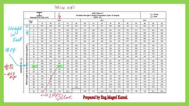
We will proceed directly to table 4.1, FE Exam Ref book. We have our KyL= 1.2x 15=18 feet, mark the value.
Fy is 50 ksi.
One remark is that the table is assigned only when the yield stress Fy =50 ksi for other values use table 4-22, with the intersection of the horizontal line of 18′ with the vertical line for W14x61.
We have completed solving the solved problem after changing the section to become W14x61. To prove that The result from the table coincides with the calculation.
For the traditional way of calculation. We will estimate whether the column is long or short by using the formula for the value of (k*l/r), which will give ( 4.71sqrt(E/Fy)), will give=4.71sqrt(50000/50)= 113.43.
The same procedure for our Ky*ly/ry from the previous calculation is smaller than the 4.71sqrt(E/fy), the column is short.
Proceed for Fe estimation which is =36.856 ksi.
But fcr will be estimated by using the formula, 0.658 ^ (50/36.856)* 50=28.337 ksi.
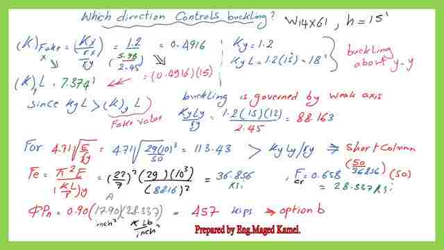
ry = 2.45 inch 2, for that section, but still, the k equivalent for the x major axis *(L) is s< ky* ly, so the weak axis controls the load, explained as follows:
A-Ky equivalent=k/(rx/ry)=(1.2/5.98/2.45)=0.4961, then again to be multiplied by the column height which is 15 then =0.4961*15=7.374 ft.
b-Our ky ly= 18 ‘ which is > 7.374 ‘. ky*ly/ry= 88.163 and 4.71*sqrt(E/fy)=113.43 which is constant for Fy=50 ksi.
C-The Euler value is =36.856 ksi. Fcr= 0.658 ^(50/36.856)* 50=28.337 ksi.
Fcr will be multiplied by φ *area it will be equal to (0.9×17.9×28.337)=457 kips so option b is correct. This answer matches the answer obtained previously.
Another solved problem 13-29 for column analysis.
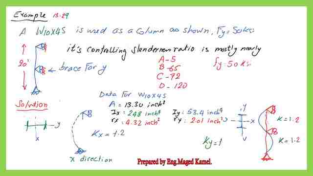
Another solved problem is 13-29 for column analysis from M Iqbal’s book. The column given is 20 ft tall and pinned at the bottom and top, but for the y-direction has roller support at the mid-height regarding the x-direction, we have only supported at the bottom and top.
The section is W10x45, fy=50 ksi, it’s controlling slenderness ratio which is K *Lvalue/r is mostly,5 or 65 or 72 or 120.
The solution is based on y-direction k is taken as 1.2.
while for the x, the column height is 20 feet and k was also taken as 1.2.
Why the selected value is 1.2?
A reference for the k value-based on different end conditions.
I have searched for the reason by referring to the e funda – engineering Fundamentals -which includes free- free, Kl= 1.2L, while hinged -free, which is our case the KL is also 1.2.
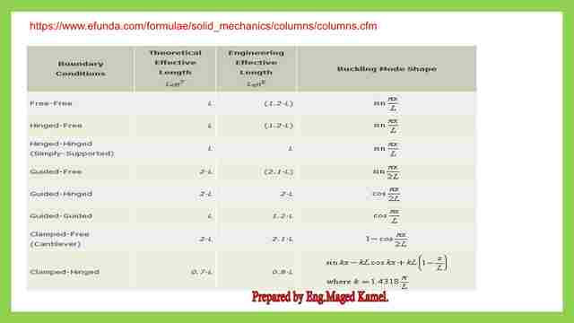
In the y-direction, hinged free, then 1.2 for- k is selected, but the length is 10 ft, while for k value for x is 1.2 but the length is the total length.
The information for W10x45 is as follows, the area is 13.3 inch 2, Ix= 24.8 inch4 and rx= 4.32 inch 2, Iy= 53.4 inch2 and ry= 2.01 inch 2, this is a section sketch in the y-direction. The buckling shape can be imagined as pressing perpendicular to the y-axis, and the buckling shape for the x-direction can be imagined as if pressing perpendicular to axis x.
Again we will convert the kx into a fake or equivalent by/ rx/ ry, kx which is 1.2, referring to the values of rx,ry.
kx =1.20 / (4.32/2.01) = 0.558 *20= 11.17 ft .
While the ky = 1.2, Ky*Ly=1.2*10=12 ft, since the equivalent, Kx*Lx is < Ky *Ly. The buckling is controlled by the minor axis, then the controlling slenderness ratio is( ky*ly/ry).
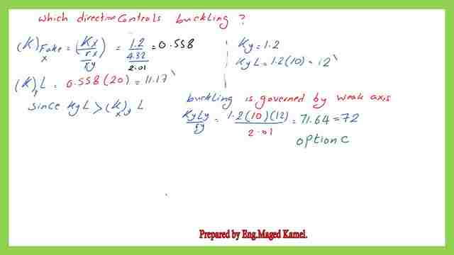
Referring to the options numbers ky*ly/ry, which will give the value of 71.64 nearly 72, which is option C.
This is the pdf file used in the illustration of this post.
The next post is Introduction to Local Buckling.
For an external resource, this is a link for this post, Concentrically Loaded Compression Members.