
Collapse load for indeterminate beam.
What is the difference between the equilibrium or static method and the kinematics or mechanism method? From Prof. Capprani’s structural analysis III.

The Collapse load for indeterminate beam by the statical method.
We want to estimate the collapse load for an indeterminate beam. which has fixed support at point A and roller support at point B, which is statically indeterminate of degree-1. There is a P load at point C at a distance of L/2 from the left support.
It is required to estimate the collapse load P collapse and plastic moment Mp and find out their relation, by using the static method.
For the static method, the value of M -ve at the left support should be known, the bending moment is to be drawn, and the sagging moment of PL/4 to be subtracted from the moment value as will be shown to get M+ve. value.
It is required to estimate the collapse load P collapse and plastic moment Mp and find out their relation, by using the static method.
For the static method, the value of M -ve at the left support should be known, the bending moment is to be drawn, and the sagging moment of PL/4 to be subtracted from the moment value as will be shown to get the positive M+ve. value.
The Fixed-beam at A and with roller support at b is considered as a combination of two beams or Superposition of two cases, the first case where a simple beam acted upon by load P and the second case, due to fixation at A, Moment M will act at the left support A.
Then, we add these two cases to get the final moment diagram. At support A, we have Ma=(3/16)*P*L.
and zero value at B. and for the load case, we have moment value =P*L/4, due to the Reaction at A=P/2, causing moment=(P/2*L/4)=P*L/4. The final moment at c=P*L/4-(0.50)*(3/16)*P*L=(5/32)*P*L.
The proposed positions of plastic hinges.
The load P is applied gradually until the value of the P collapse is reached, that P collapse creates M-plastic at the fixed end.
Let us check the mechanism of collapse. We have A as fixed support with 3 reactions, and there is roller support with one reaction only, adding together we will have (3+1)=4.
We have one degree of indeterminacy. Add 1 to this one-degree indeterminacy. Then the number of hinges required to create collapse to that system is =2.
The proposed location for the first hinge is at the location of load that creates a maximum moment, the first hinge will be placed at point C and the second hinge to be located at the fixed support, so we have two hinges.
The direction of Mp is at the fixed-end is anti-clockwise, while the second Mp is at the middle of the span, at point C. Here is the sketch of the two moments.
The next sketch is created by placing the two diagrams together. On joint A we have Mp value and Mp= zero at the other joint, and for the +ve moment, we have 0, at point A, PL/4 at point C, and zero at point b.
Check the moment at C, (1/2Mp)+Mp positive at b, we add (1/2Mp)+Mp=(P*L/4). While applying P, Mp -ve at the support A is created first, then further increase of load, then M positive reaches Mp at C, the total positive moment =P collapse*L/4.
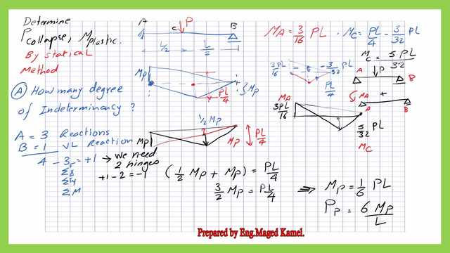
Then (0.50Mp+Mp)+ Pp*L/4, 2 will go with 2, Mp=(1/6)*Pp*L. The Plastic Load or the collapse load Pp=6*Mp/L.
The Collapse load for indeterminate beam by the kinematic method.
To create collapse, two hinges will be placed, the first one will be at point A and the second one will be at point B. due to the acting P collapse load, deflection Δ will occur, and failure will happen.
The mechanism of failure is due to the two hinges, at the collapse, there will be angle θ, at the collapse, there will be angle θ at both points A, B. θ= tan(θ), since the angle is small. Accordingly, θ= tan θ=(Δ)/(L/2), there is symmetry at point C.
The external work PpΔ= internal work=Mpθ+Mp(2θ). PpΔ=3Mpθ.While θ=2Δ/L, Pp==6*Mp/l, which is the same result obtained from the static method.
To determine the reactions, due to acting load P. Two reactions of P/2 at the two supports will exist but due to Mp another reaction will be created, an upward reaction at A, Ra=M*P/L to resist the end moment at A.
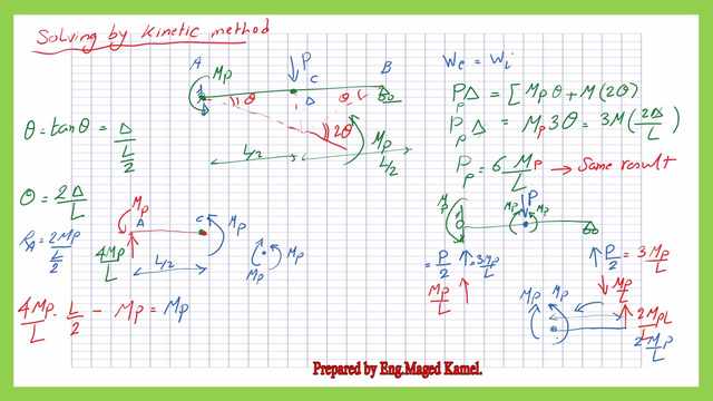
Rb=M*P/L acting downwards to resist the anti-clockwise moment Mp. Taking the Moment at joint B, Mp acting in anti-clockwise, Ra= P/2 +M*P/L.
Expressions for the plastic theory.
The first expression is the load factor for a possible load mechanism. λi lambda i, which is the collapse load divided by the working load to reach Mp, the loads are applied gradually, till the value of Pp=Pw*λi is reached. Mp is given as 9.0 KN.m.
the second expression is the F.O.S= First yield load/ working load.
We have estimated the plastic load as Pp=6*Mp/L, L=1.00m, Pp=6*9/1=54 KN.to estimate the F O S= First yield load/Working load.
We need to estimate the Py, The joint A has yielded first, create a hinge at A., the moment at A should exceed My and has Mp, for further increase in load, Mp can not be exceeded at joint A, but Mp will be created at point C. So My occurs first at joint A.
For My value at joint A, if the yield load is Py, M-ve at the fixed end at yield My=3/16 Py*L, the positive value of moment at point C My=(5/32)*Py*L.
Consider My=(3/16)PyL, to find the value of Py, consider My=7.50KN.M, L=1, Py=(7.5016)/3=40KN. If we place a yield load at C, Py=40 KN, M+ve at point C= M=(5/32)PyL=5/3240=200/32=6.25 KN.M<My.
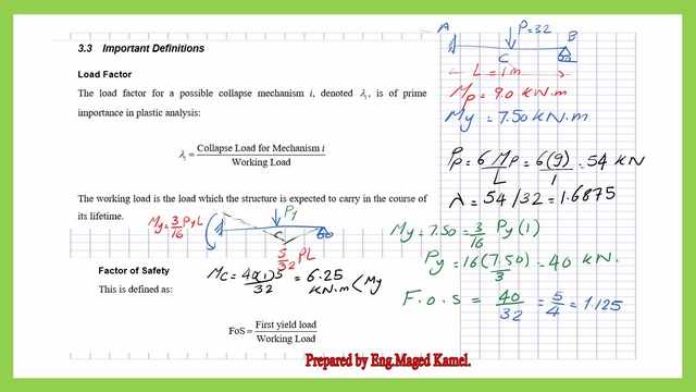
The Factor of safety = =P-first yield /P working=40/32=5/4=1.125.
This is the pdf file used in the illustration of this post.
For useful information about the structural analysis -III.
The next post is about the upper-bound definitions. The post is an introduction to the theory of upper bound.