A solved problem 2-22 for structural steel -shear stress estimation-part 2
A solved problem 2-22 video.
We continue the solved problem 2-22 for the shear stress of the other shapes I shape and the steel W section. This is a link to the video to watch in youtube channel.
I have made some modifications to the content of the pdf.
This is a solved problem 2.22; it is required to estimate the shear stresses for three different items. Part A was discussed earlier.
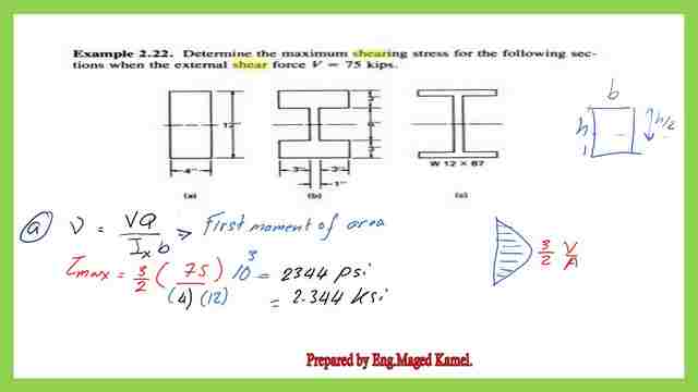
For item b, for the I section with thickened flange, the maximum shear stress will occur at the neutral axis.
The Q, the first moment of the area at the N.A=sum(QF+Qw) at the N.A, the estimation are shown in the next slide, also the evaluation of Ix is also shown.
Q is the product of the area by the distance to the neutral axis, for the flange, its width=7″ and thickness=3″, the Af=21.0 inch2, the CG distance to the N.A=(0.50*6+1.50)=4.5″, Qf=21*4.50=94.50 inch2.
While for Qw=Aw/2*hw/2=6*1*(1/4)*3=4.50 inch3, so we have two values for shear stress, the first value is due to the flange, and the second value is for the web.
τmax=V*Q/Ix*b, b is the breadth= breadth at the neutral axis=1″, Ix=900 inch4, V=75 kips, the final τmax is shown on the next slide. The value of τmax=(94.50+4.50)*75/(900)*1=8.25 kips/inch2
The shear distribution is shown as τ=0 at the top, and the value at the lower edge of the flange=94.5075/(900)7=1.125 kips/inch2.
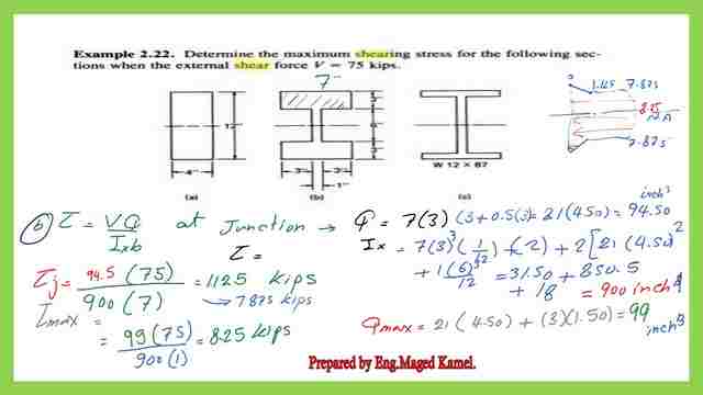
Immediately under the flange, the width gets decreased from 7″ to 1″, the shear stress value will jump and will be multiplied by 7, and the width considered is 1″ instead of 7″. The value of shear is just below the flange=7*1.125=7.875 kips/inch2.
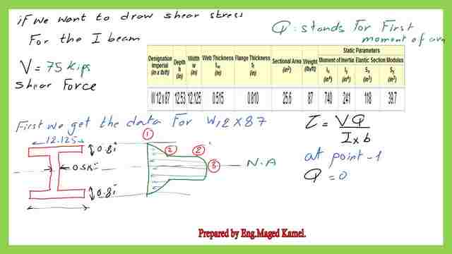
Shear stress diagram for part c of the solved problem 2-22.
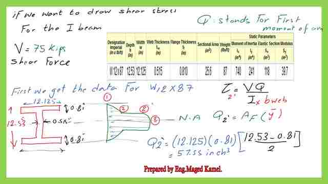
For item C, in the solved problem 2-22. For the I section W12x87, the relevant data was obtained from table 1-1 for the depth of both flange and web thicknesses. the width of the flange=12.125″ and its width=0.81″.
While the web thickness =0.515″. The overall height of the W section =12.53″.Ix=740.0 inch4.
If we wish to draw the shear stress at points 1-2-2′ and 3, we will proceed as follows:
For point 1, the moment of area=0.
For point 2, the moment of area=Af*y CG to the N.A, the breadth=bf.
For point 2′, the moment of area=Af*y CG to the N.A, the breadth=bw.
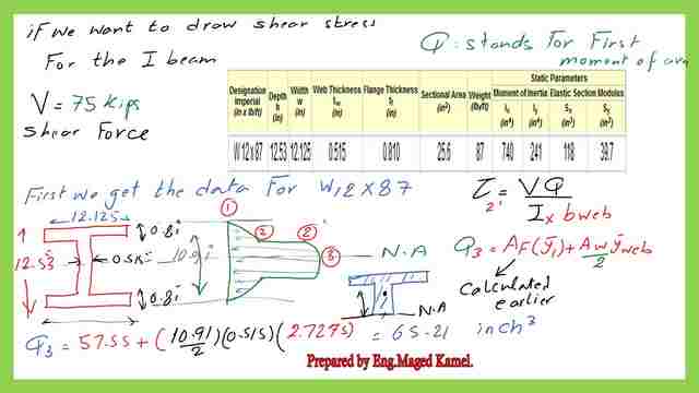
For point 3′, the moment of area=Af*y CG +(A web)/2*ycg to the N.A, the breadth=bw. All the calculations are shown in the next slides. The shear stress τ at the top at point 1=0, no area to be calculated.
The Q value at point 2, for the solved problem 2-22 Q2=(12.1250.81)=9.82 inch2, the Cg distance to N.A=(12.53-0.81)0.50=5.86″.
Q at point 2=9.82*5.86=57.55 inch3.

The Q value at point 2′, Q2’=(12.1250.81)=9.82 inch2, the Cg distance to N.A=(12.53-0.81)0.50=5.86″.
Q at point 2=9.82*5.86=57.55 inch3.
For the Q value at point 3, we will add the area of the half web multiplied by the Cg distance to the previous estimated Q2, so Q3=57.55 inch3+Q from half of the 7.66 inch3, Q3=57.55+7.662=web which Aycg=0.50(12.53-20.81)0.515*2.7275=65.212 inch3.
For every Q will multiply *V and divide by Ix *width. the relevant values of shear stresses are estimated in detail and shown in the next slide image. Among the various value of shear stress, we will find that the maximum value occurs at the N-axis.
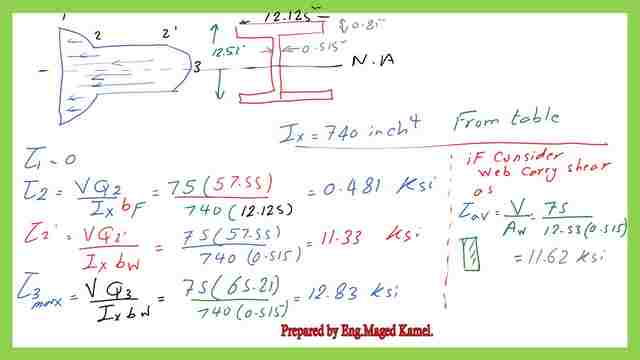
The max shear stress value =12.83 ksi at the N.A. If we evaluate as the web will carry the shear then the average stress=11.62 ksi is shown.
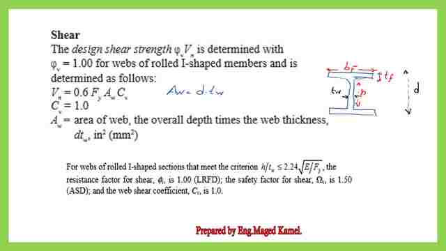
AISC provision for shear.
The code specifies certain criteria for h/tw should not be <2.24*sqrt*(E/Fy), the Vn equation is shown. Aw=d*tW.
These are the relevant values for h/tw based on different values of ASTM. The list includes carbon steel Fy=36 Ksi ASTM A36 min Fy=36 ksi, Tensile= 58-80 KSI.
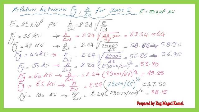
For high-strength alloy ASTM A572 the 5 steel grades of 42, 50, 55, 60, and 65, Fy from 42-65 ksi. For ASTM A 514 Fy=100 KSI.
This is the pdf file used for the illustration of this post.
In the next post, a solved problem 10-2 for beam adequacy for shear.
For a good reference-Shear Behavior. in Chapter 8 – Bending Members.A Beginner’s Guide to the Steel Construction Manual, 14th ed.