A Review of Portal frames-pin supports at base.
We stopped at the end of the previous post while discussing the approximate method for the portal frame. How to make a structural analysis, and we give an example, as we have a frame that has two hinged supports and is acted upon by a force at the left side.
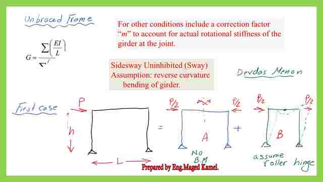
The Portal frame is analyzed into two frames.
The frame can be analyzed by dividing the frame into two parts, the first part has antisymmetrical loading and the second part has a symmetrical loading, and due to that loading the elastic curvature.
We can assume that we have roller support in the middle of the girder. In the next slide, after we have created roller support in the middle of the girder, the support reactions.
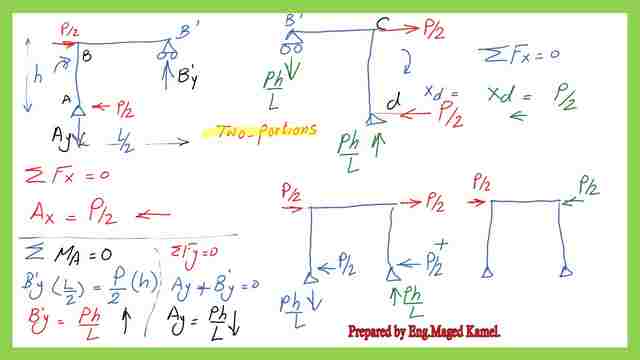
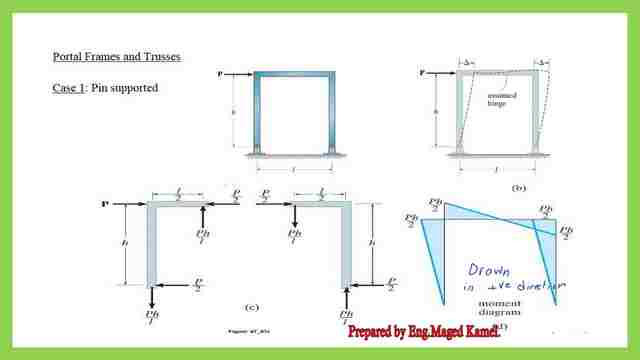
If we consider, the portal frame height is h, the lower joint is A, the upper left corner is b the right corner is c and the last support is D.
Estimation of the portal frame reactions.
The roller support distance is at L/2, and this is the continuation of the frame If we have a look at the left side portion, where we have P/2 at the left side from left to right and other load P/2 at the right joint acting to the right, from the sum of forces at the x-direction ∑Fx=0, ∑Fy=0, ∑M=0.
We can be able to determine the magnitude of the reactions, for the lower hinged support and also for the roller support at B’, since the hinge at A can take the horizontal force, since the roller support at B’ can not take that force so, Ax=P/2, so ∑Fx=0 is utilized.
The reaction Ax is to the left, Taking bending moment at A =0, then the Vertical reaction at B’ can be estimated B’y*L/2=P/2*h, B’y=(P/2)*h/(L/2)=B’y=P*h/L=P*h/L, due to the summation for moment =0.
From ∑Fy=0, since no external forces at the Y direction, then Ay will be =b’y=P*h/L but acting downwards, at B, force B’y acting upwards, at the joint, at the right side there will be a force= P*h/L acting downwards, then the reaction at d will be P*h/L acting upwards since we have a force at joint P/2 acting to the right, for ∑Fx=0, at support d, the joint force Xd=P/2, acting to the left. We can get the reaction for the first part, the horizontal reaction at A is P/2, and at D also=P/2, while the vertical reaction at A is Ph/L, downwards, and the vertical reaction at d is Ph/L, upwards. For the other frame, we have P/2 and P/2 as joint loads.
After summing the two frames, we can get the final situation, the normal force diagram, the shear force diagram, and the moment diagrams.
How to draw internal forces diagrams of the portal frame-pin supports at the base?
We have tension force=p*h/L, for column AB, at joint b, the compression force for member bc will be (P-p/2)=p/2 acting at joint c, then We have compression force=P*h/L acting at joint D for the member DC. That was a review of portal frames that have two-hinged support.
For the shear force, at joint A we have positive force=P*h/L, which will act till the joint. The P*h/L acting anticlockwise will create a negative shear for member BC, from D to C we have a negative shear force = P/2 till joint C.
For the bending moment diagram, we have a moment at joint b=P/2h, at the corner, there is a moment. at the middle moment=0, then continue to joint C the value is Ph/2.
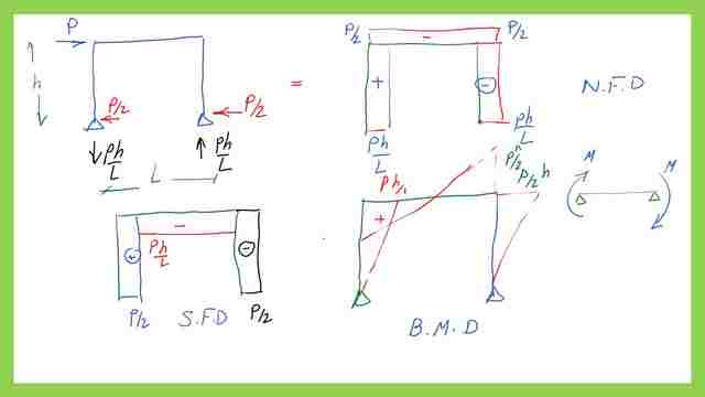
The value of m=0 at joint D will remind us of the double curvature where we have two equal moments in the same direction. The same result is also shown in these diagrams, but I have explained in more detail, the bending moment diagram is drawn on the positive side.
This is the pdf file used in the illustration of this post and the next post.
This is a link to A very useful external link is Concentrically Loaded Compression Members.
This is the next post, Analysis of portal frame-fixed supports at base.