How to design a beam using design chart with given lr?
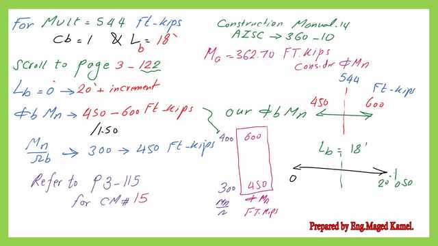
It is required to design a beam section for cb=1, Fy =50 ksi, under Ultimate moment Mult= 544.0 ft kips, Ma=362 ft-kips, and given bracing length Lbr=18′.

Discussion of Table 3-10, design chart.
Table 3-10, design chart, from the construction manual-14, The end page for W sections is at page 3-134, for the design of W- sections, the page contains at the left side φb*Mn for the LRFD design and Mn/Ωb for ASD design. While for CM#15 the page is P3-127.
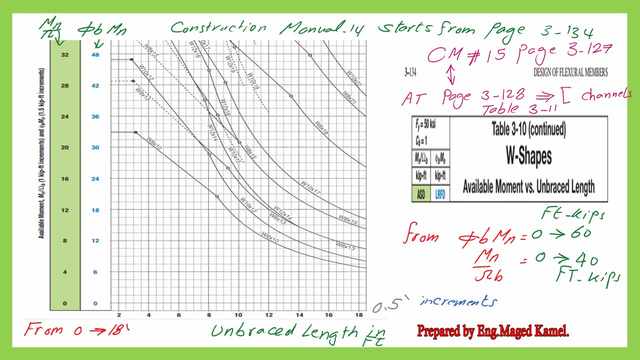
The value of φb*Mn starts from 0 to 60 ft-kips & for Mn/Ωb, it starts from 0 to 40 Ft-kips, accordingly, since φb*Ωb =1.50. As for the bracing length, lb, it starts from 0 ft to 18′ as shown in the next slide.
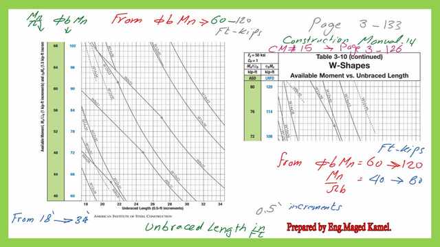
For page P-3-133 from CM #14 and page 3-126 from CM#15. The value of φb*Mn starts from 60 to 120 ft-kips & for Mn/Ωb it starts from 40 to 80 Ft-kips, accordingly, since φb*Ωb =1.50. As for the bracing length, it starts from 18 ft to 34′ as shown in the next slide image.
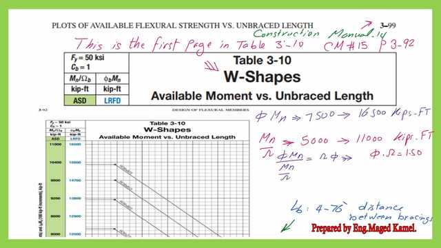
This is the first page of Table 3-10 on page 3-92 from CM#15. for the design of W- sections, The value of φb*Mn starts from 7,500 to 12,000 ft-kips & for Mn/Ωb it starts from 5,000 to 8,000 Ft-kips, accordingly, since φb*Ωb =1.50.
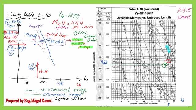
For Mult=544.0 ft-kips and cb=1, lb, the bracing length=18′, the appropriate page is page No.3-122, from which φb*Mn starts from 450 to 600 ft-kips & for Mn/Ωb it starts from 300 to 450 Ft-kips, lb from 0 feet to 20′.
How to get the proper section for a beam, by using the design chart-AISC table 3-10?
The following steps are shown in the next two slides, draw a horizontal line for the value of Mult or φb*Mn=544 ft-kips between φb*Mn =450-600 ft-kips.
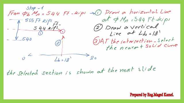
Step 2: Draw a vertical line from lb=18′, at the intersection of these two lines, select the first solid line on the right side, do not select any dotted lines, since these lines represent an uneconomical solution.
The following steps are shown in the next two slides, draw a vertical line for the value of lb=18′. check the first solid section which will be W24x88, the section will give a value if the factored moment=544 Ft.kips.
Comparison between using Table 3-10 and use of Table 3-2.
Now, suppose that we are going to design the steel beam as a W-section by using Table 3-2, as the selection is by z section, what will be our procedures?
The first choice for the design of a steel beam.
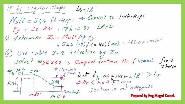
1- Get the Z value of the section based on the relation Zx=Mult/Φb*Fy, which as per the given data will be 145.0 inch3.
2- Proceed to table 3-2, to select a higher value of Zx, which is >145.0 inch3.
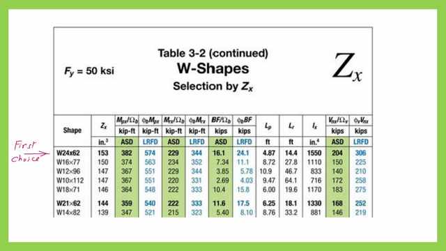
Our first choice will be W24x62, which has Zx=153.0 inch3, but from the same table, for that section.
Our Lp=4.87′ and Lr=14.40′, with a given Φb*Mn=570.0 ft- kips for Lp=4.87′, and Φb*Mr for Lr=344 Ft-kips.
This section is not suitable since lb is 18 feet and the required Φb*Mn=544 ft- kips, which is bigger than 344 Ft.kips. Please refer to the next slide for more details.
Please refer to Table 3-2 for the relevant data for section W24x62.
3-Since our lb =18′, which is > Lr, the section carrying capacity is <344 ft-kips, but our given Mult is 544 ft-kips, so the section cannot carry the given Mult, so this option is not satisfactory.
The second choice for the design of a steel beam.
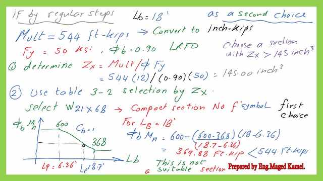
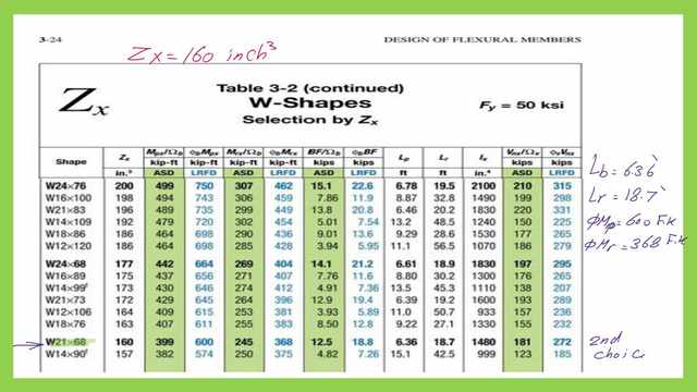
1- For the second option, we proceed to W21x68 with Zx=160.0 inch3, but from the same table, for that section, our Lp=6.36′ and Lr=18.70′, with a given Φb*Mn=600.0 ft- kips Lp=6.36′, and Φb*Mn for Lr=368 Ft-kips.
2- Since our lb =18′, Then the Φb*Mn is between 600 and 368 Ft-kips, exactly =369.0 ft-kips, which is <Mult=544.0 Ft-kips, so again, the section can not carry the given Mult, then this option is not satisfactory.
Please refer to Table 3-2 for the relevant data for section W21x68.
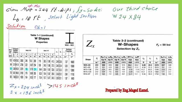
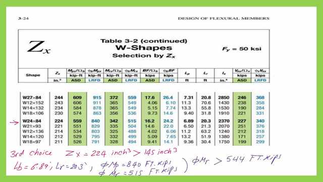
The third choice for the design of a steel beam, this choice complies with Table 3-10.
This is the relevant data for the third choice w section from Table 1-1.
Please refer to Table 3-2 for the Lp and Lr data for the W24x84 section.
For the third option proceed to W24x84 with Zx=224 inch3 > 145.0 inch3, but from the same table, for that section, our Lp=6.89′ and Lr=20.30′, with a given Φb*Mn=840 ft- kips for Lp=6.36′, and Φb*Mn for Lr=515 Ft-kips.
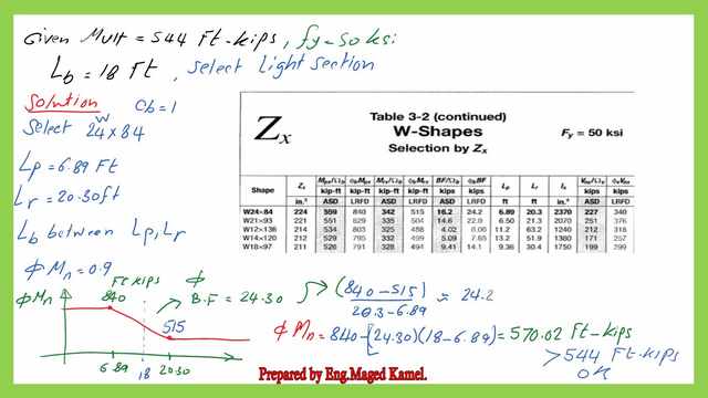
LRFD design data for W24x84
Remember this choice matches the use of a graph, and the same value of Φb*Mn=570.0 ft- kips, we have obtained from 3-10. Select W24x84 for cb=1, the plastic length lp=6.89 ft, and lr=20.30 ‘.
Our given lb=18′. We can estimate the bending factor BF from the slope and get the factored moment for the section. It can be found to be 570.0 ft. kips
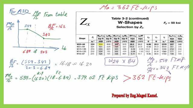
ASD design data for W24x84
Select W24x84 for cb=1. This is the check for the ASD, the selected section will give a carrying capacity of Mn/Ω=379 Ft-kips>362.0 Ft-kips as given. Mp/Ω=559 ft. kips and Mrx/Ω=342.0 ft.kips
This is the pdf file used for the illustration of this post.
For more detailed illustrations for the CB, please follow this link Flexural Limit State Behavior.
For the next post, Solved problem 4-7-design using table 3-10 when Lb>Lr.