A Solved problem 5-3 for local buckling of columns.
Review of the equation used to differentiate between long and short columns.
As a review, first, we have to check that, the column is long or short, by using equation 4.71sqrt(E/Qfy), in the case of KL/r >4.71sqrt(E/Qfy).
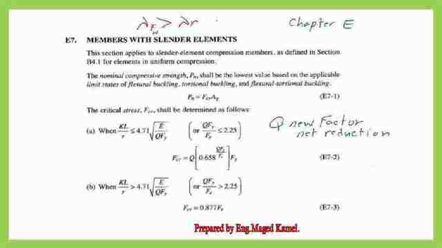
The column is long. if kl/r> 4.71*sqrt(E/Q*Fy), else the column is short if the K*l/r<=4.71*sqrt(E/Q*fy).
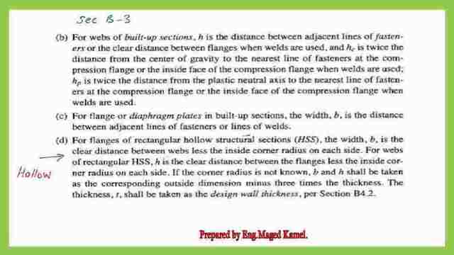
If the column is short, proceed to check the local buckling. For the flange and web, in our case, the hollow steel section is a stiffened element, only one equation will be used. Refer to item d, See B-3, which includes, how to measure the b length of HSS, and the definition of both b and h.
A Solved problem 5-3 for local buckling.
For the solved problem 5-3, An HSS section 16x16x1/2 inch, with Fy =46 ksi, is used for an 18 feet column with simple end supports. Determine Φc*Pn and Pn/Ωc, with the appropriate AISC equations, repeat part a) Using 4-4 in the AISC Manual.
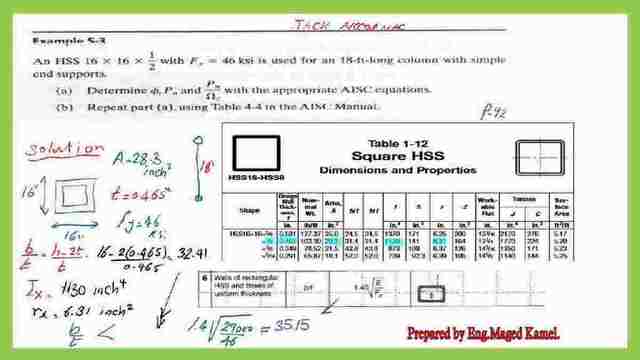
We refer to Our table 1-12 for the properties of the Hollow sections, select HSS16x16x ½, wall thickness is 0.465 inch and the area is 28.3 inch 2, fy=46 ksi, to check, b/t=h-2t/t, we have 16 inches as b, t= 0.465, then b-2t=(16-2*0.465)/0.465=32.41.
Ix = 1130 inch 4, and rx=6.31 inch2, According to item 6 for HSS, λr=1.4*sqrt(E/fy)=1.4*sqrt(29000/46)=35.15,then b/t <32.41 , the section will have QA=1 , we do not have Qs, no unstiffened section.
In the next slide, Check for short or long column criteria, by using equation 4.71*sqrt(E/fy)= 4.71*sqrt(29000/46)=118.26, while Kl/r,rx=ry=6.31 inch2, KL=1*18 *12, for inch, then (18*12/6.31)=34.23, which is < 118.26 the column is short, and non-slender element.
We will estimate Fcr =0.658^(46/Fe)*fy, with no Q in the equation since Q=1. We need to estimate Fe, Fe=Pi^2E/(KL/r)^2, Fe= (22/7)^2(29000)/(34.23)^2 =244.4744 ksi, back to fcr=0.658^(46/244.4744)(46)=42.516 ksi.
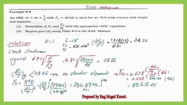
Then for LRFD, ΦFcr for ASD, use Fcr/Ωc. For the Pn= =FcrA=42.516*28.23=1200.2 kips, for LRFD, our Φc=0.9.
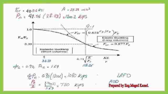
Then Φ*Pn=0.9*1200=1080 kips. for the ASD, since Ωc=1.67,Pn/Ωc=1200/1.67=720 kips.
Using table 4-22 as an additional option for solved problem 5-3.
For table 4-22 for available critical stress for compression members, page 4-322 Aisc 14 edition manual, we have kl/r=34.23, from fy=46 ksi, From the left side of the table, log in with 34.24, in between 34 and 35, for kl/r=35, we have 38.3 ksi, while for kl/r=34 38.1, by interpolation our final value ΦFcr=38.254 ksi, that is the stress value
To convert it as a load multiplied by the area which is 28.3 inch 2, or Φ*Pn=1083 kips, can be approximated to 1080 kips, similar to the one estimated using the hand calculation for the LRFD.
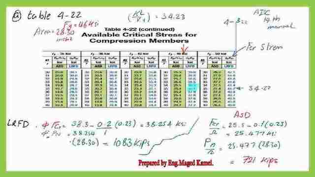
From Table 4-22, The stress, Fcr/Ω is between 25.5 and 25.4, by interpolation= 25.477 ksi, by interpolation= 25.477 ksi, then multiply * area which is 28.3 inch2, Pn/Ω=721 kips, same as the estimate earlier. The values were driven first by using equations, then by using Table 4-22.
Using table 4-4 as part b for the solved problem 5-3.
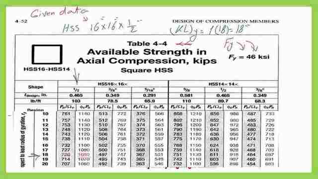
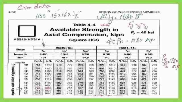
For part b, where it is required to use table 4-4, table 4-4 is for the square HSS, we have Fy=46 ksi, HSS is 16x16x1/2 inch, we have K*l at y direction =18′. We can log to table 4-4 and select kl at y=18′ then from the column 16x16x1/2″, we get the LRFD and ASD values for the column, please refer to the next two slides.
This is the calculation for the load based on the ASD design.
This is the pdf file used in the illustration of this post.
If you wish to refer to the previous post: A Solved problem 5-2 for local buckling of columns.
For a good external reference, find this link–Chapter 7 – Concentrically Loaded Compression Members.
This is a link for the next post, solved problem 6-8