
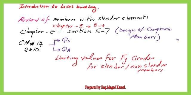
Local Buckling for stiffened and un-stiffened elements.
Local Buckling for stiffened and unstiffened elements.
Our subject is the Local Buckling for stiffened and unstiffened elements. sections are classified as non-slender elements or slender elements. Some chapters we need to check especially Chapters B and E.
For non-slender elements, We have two factors, one factor for flange and the other for the web. if the b flange / t flange < certain ratio λr, then the section is the non-slender.the ratio, which we have already talked about via tables.
Chapter B deals with design requirements, part b4 will give information about the classification of elements for local buckling. here is a snapshot of the summary of the content of Chapter B.
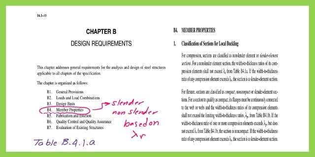
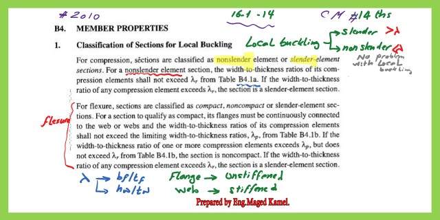
the next slide shows in more detail the classification of sections for local buckling. there is table B4.1a that specifies the sections based on stiffened and non-stiffened elements.
h web/ t web < λr for a certain factor then the section is non-slender, if > λr As shown in the table, then the section is slender, then a reduction of the coefficient.
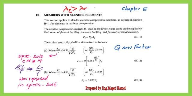
This is a .part E7 concerned with members of slender elements. slide image for the summary of chapter E for the design of members for compression

There are two coefficients, the first one is Qs and the second coefficient is Qa, the Qs is for the flange, if the lambda λ, is bigger than the ratio given. While the Qa is for the effective area/ A gross. Non-slender not exceeding λr, from table B4.1a.
Pn, the nominal compressive strength shall be the lowest value based on the applicable limit states of flexural buckling, Pn=fcr*Ag.
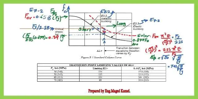
First, the column to be checked is a Long or short column, but the formula used, will be KL/r<4.71*sqrt(E/FY).
Q=QsQa or Q*FY/Fe< or=2.25 then the Fcr can be Fcr=Q(0.658^QFy/fy)fy =Q(0.658^QFy/fy)fy, but if Kl/r>4.71*sqrt(E/Q*Fy), the Fcr=0.877 Fe.
Let us look at the Kl/r=4.71*sqrt(E/Qfy), How was the equation derived?
Consider QFy/Fy when Q=1, and when Fy/Fe=2.25,again when shifting( Kl/r)^2=2.25*(pi^2*E/fy).
Take the SQRT (Kl/r)^2, gives ( Kl/r)= SQRT(2.25*pi^2*E/fy)=SQRt of (50), this 50 = pi^2*2.25, which is = 7.41.
So we come to our equation of 4.71*sqrt(E/Fy), which defines whether the column is short or long. K*l/r is shown as a vertical line in the graph.
If the column is long the fcr=0.877 *Fe, and the table lists the different values of Fy For instance, for fy =36, then the limiting Kl/r=134, while for Fy=50 ksi.
Limiting Kl/r based on the different Fy values.
If the column is long then fcr=(0.877 *Fe), The table lists the different values of Fy, for instance, for Fy =36, then the limiting Kl/r=134, while for fy=50 ksi, the limiting Kl/r=113, for fy=60 ksi, then the limiting case is 104, the controlling factor =4.71*sqrt(E/Fy), and the corresponding values of the values of 0.44 Fy are all listed. The ratio of (K*L/r) was replaced in specification 2016 by Lc/r.
If the column is long, then the graph is the black-shifted curve from the dotted Euler graph. 0.877Fe, let us have a look at the Euler graph the ordinate is fcr when is =fy/2.25.
Draw a horizontal line from that point that intersects with the Euler curve at 7.41 sqrt(E/fy), the ordinate with the intersection with the shifted curve, will be fy/2.25(0.877)=0.39 Fy.
If the Kl/r< 7.41 *sqrt(E/Fy), then the equation E 7.2 will be used as fcr=0.658^(Fy/Fe)*Fy, For Q when the equation is modified, the Q will appear with fy.
If the column is long, then the graph is the black-shifted curve from the dotted Euler graph.0.877Fe, let us have a look at the Euler graph the ordinate is fcr when is =fy/2.25.
Draw a horizontal line from that point that intersects with the Euler curve at 7.41 *sqrt(E/fy), the ordinate with the intersection with the shifted curve will be fy/2.25*(0.877)=0.39 Fy.
If the Kl/r< 7.41 *sqrt(E/fy), then the equation E 7.2 will be used as fcr=0.658^(Fy/Fe)*fy. For Q when the equation is modified, the Q will appear with fy.
Parameters for local buckling for Unstiffened elements.
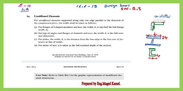
for the Local Buckling for stiffened and un-stiffened elements., especially for the unstiffened elements, the elements, for instance, are free on one side, and fixed on the other side, same as flanges, the ratio of bf/2tf, the C channel, and the outer portion.
A- For flanges of I-shaped members and tees, the width b is (1/2)of the full-flange width, bf/2tf, as for legs of angles and flanges of channels and zees, the width b, is the full nominal dimension, b/tf.
B- C-channel has only one part, so no division by 2 as compared with I-shaped sections. The factor for Qs for b/t is an indication for slender if exceeds certain criteria, or if less then can be considered as non-slender.
For hot rolled when b/t<= 0.56 *sqrt (E/Fy), then the Qs is =1, but if b/t > = 0.56*sqrt (E/Fy) and < 1.03 *sqrt (E/Fy) and < 1.03 *sqrt (E/Fy.
The Qs can be given as per the equation of E 7.5, but if b/t > = 1.03 *sqrt (E/fy) then Qs can be evaluated from E7.6.That was for the Qs for flanges.
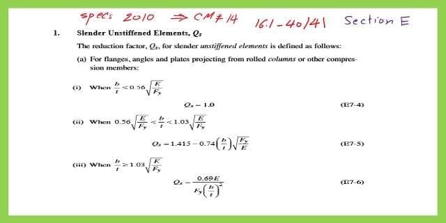
Table B4.1a for un-Stiffened elements part.
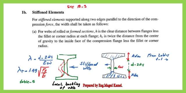
This is a part of the un-stiffened elements in the web in an I-shaped section, the web is stiffened by the upper and lower flanges as shown.
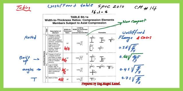
The height for estimating the ratio, full height of the section -2 ks, where ks is the distance of the fillet or corner radius at each flange. From table λr = 1.49*sqrt (Fy/E).
Table B4.1a for Stiffened elements part.
The stiffened elements are listed from no 5 to no.9.
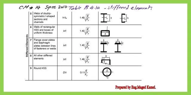
Refer to the table from case no 5 for I beam sections for stiffened elements.
The Qa is given by For E 7-16 &E7-17 is used for the QA, The Qa is the factor relating to the web. A stiffened part, Qa=Ae/Ag, effective area / gross area after checking b/t value.
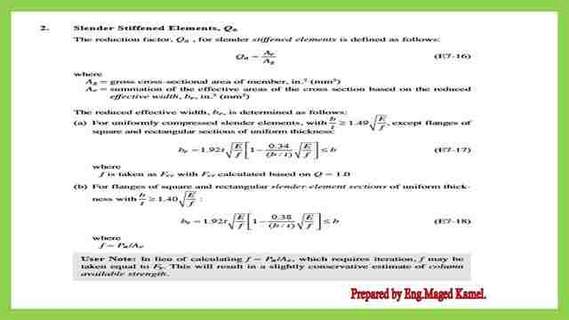
For the web of I section > 1.49 sqrt(E/fy) or equal, be was b-2ks, will be modified, the be will be determined from equation E 7-17, this equation based on Qa =1.
First, we start with the flange to evaluate the relevant Qs, assuming that Q=1, from the graph we will estimate the f value as Fcr, as we will see later, f is taken as Fcr with Fcr calculated based on Q=1.
This is the pdf file used in the illustration of this post.
This is a link to Solved problem 5.2, from Prof. McCormac’s handbook, which will be our next post.
for a useful reference, Limit State of Flexural Buckling for Slender Sections